Glowing Core shader breakdown

In this blog post, I'd like to take a closer look at a surface shader I recently created in Unity's new Shadergraph for Hands Up!, a musically infused climbing game. Inspired by the look of the glowing buttons of launch pads used in music production, the shader lets an object look like frosted plastic with a LED inside. It's a pretty simple one, so I thought it would make a great first tutorial for this blog.
The heart of the shader is what is commonly known as a sphere mask. It returns a value between 0 and 1 depending on the distance of a given 3D position and a center point. The function returns one in case both positions are equal and values closer to zero as their distance reaches the value of the radius parameter (see the formula underneath, the saturate function simply clamps values to the range [0,1]).
Out = 1 - saturate(distance(Coords, Center) - Radius);
Remember that the whole shader gets executed for each fragment (basically a visible position on the object's surface) with its corresponding position. So when we now feed in the fragment position in object space as the Coords input and leave the Center constant at (0,0,0), every point on the object's surface gets shaded according to its distance from the object's pivot point ((0,0,0) in object space). This center point is the position of our LED light. In the shader graph screenshot, you can see that I swapped the subtraction order, added an additional glow strength multiplicator and took the whole result to the power of 4. This is to save a few calculations for this use-case and make the falloff between 1 and 0 look smoother.
 Modified sphere mask implementation in Unity Shadergraph
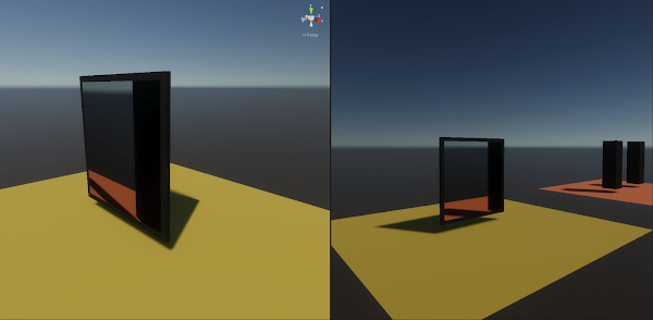
 The brightness of every surface point shows its closeness to a 3D center point. Note how the glow centers on each face do not line up yet.
This is not enough though to achieve the effect of light emitted from a center point, permeating through the object's semi-translucent material. A backlit lampshade would maybe look like that, but not a light source in a solid object. The shader looks more realistic when all the bright spots visually line up in front of the light source. To bring the effect home, we use a cheap trick. We offset the Coord position input by the view direction in object space. Think of it as the direction from a point on the object's surface to the camera position, both measured in object space. This causes the Coord position to be pushed away from the camera, along the line of sight between the camera and surface position. Points in the image center thus get pushed closer to the sphere mask center and are consequentially rendered brighter, whereas surface positions visible closer to the image borders are pushed further away from the sphere mask center and are thus rendered darker. All in all, this causes the light's glow to stick to the image center as we rotate the object or the camera around it, as though the light rays travel on a direct path from their source to our eye. But when we face an object's corner directly, the fragment in the image center is still rendered subtlety darker than its neighbors, because it's further away from the light.
 The view direction is now subtracted from the position input for the sphere mask
All that is now remaining is to add parameters for our object's base color and the light's color and feed them to the master node. I also added a subtle noise to make the object look a bit more realistic. If the light's color is set to be an HDR color with increased intensity, we get this really nice gradient from black over orange to yellow, making this shader look more realistic.
 The final result. The glow center now visually stays at the object's center, even if we look at a face from a glancing angle.
 The complete final shader graph
And that's it! I hope you found that little shader tutorial useful. Let me know in case you made something interesting with it!
~David

Comments
Post a Comment