Making dynamic perspective illusions
Imagine a screen in front of you, showing the inside walls of a box. The walls shift as you walk by, making it look like you see a shelf much deeper than the display itself. The screen's content would look like a skewed mess for a second person, but not for you. From your perspective, all works out perfectly. That is basically a dynamic, digital variant of those street art floor paintings that make you believe you stand in front of the Grand Canyon when actually, you're standing in just the right spot of your hometown's shopping street.
The effect can be archived with a device that can track your head (such as a Kinect) and a real-time 3D engine. But before I explain my setup, it's helpful to first talk about a closely related effect: a portal. More specifically, a window through which you can see (and seemingly step into) another environment. The internet offers various tutorials showing how to create a portal, but all go something like this:
- Create a second camera to point at the part of the scene that should appear behind the portal
- Let that camera render to a separate buffer (Render Texture in Unity jargon)
- Create an unlit shader for rendering the portal's geometry (e.g. a quad)
- Let that shader output the said buffer, sampled with screen UV coordinates ((0,0) in the lower-left screen corner; (1,1) in the upper-right one)

Projection of display framed by points e, f, g, h.
The shader cuts out a skewed quadrangle from the image produced by the second camera, like a cookie-cutter. It has the same shape as the portal's silhouette from the player's perspective (the first camera). These UVs apply the distortion necessary to let the world behind the portal look like a continuation of the player's world from every viewing angle. Had the shader used the classical texture coordinates of a quad, it would look like the portal was a televion, broadcasting the second camera's picture.
If you create this effect in reality, your eyes become the first camera, and the display becomes the portal. The second camera is still virtual, generating the screen content. Unfortunately, we can't make your eyes render the display with a custom shader (bummer, I know). We need a different approach to create the skewed cookie cutter.

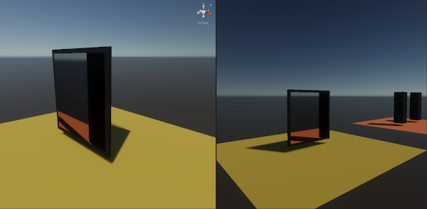
For one player the perspective works (right), for all others it doesn't (left).
The tracking device records your head's transformation in relation to itself. It moves a virtual head object as your head moves.* You must also manually match the tracker's relation to all four corners of the screen between the real and virtual world. Luckily, that relationship should never change because both devices are probably permanently installed somewhere.
When both the tracker-to-head and the tracker-to-screen relationship match, so does the head-to-screen relationship. To the virtual head object, I parented a camera that doesn't have to render anything in the final application. It's just very helpful to set up a viewport that resembles the human vision and to project points into that viewport. Those points are empty (null) objects I placed at each of the four corners of the virtual display. After projecting them onto the head camera's viewport, we obtain a point pair per corner: the screen's top-left corner (0, 0) to the top left of the display silhouette, the top right corner (1, 1) to the top right of the silhouette, and so on. We are now in UV space. Now we have to find one transformation that maps each first point onto its partner.
In 2D space, our wanted transformation is described by a 3x3 matrix. What's more, the bottom right entry is always one, leaving eight entries to find.** For that, I took inspiration from OpenCV's implementation of GetPerspectiveTransform. It constructs a linear system of equations Ax = b, whose solution vector x contains a variable for each unknown matrix entry. A is the coefficient matrix, derived by inserting the coordinates of our eight points in perspective equations. b is a second vector, containing the (also known) coordinates of the 4 skewed points, which we projected onto the camera viewport.
To solve the system, we isolate x on one side of the equation, obtaining A/b = x. However, the order of matrix multiplication is not commutative (order matters), so we don't use the division symbol. Instead, we write A-1 * b = x. That also shows that we have to find the (multiplicative) inverse of A. After multiplying it with b, we obtain a vector with eight values, which we use to construct our final transformation matrix. A function for calculating the matrix inverse is usually part of a 3D engine's API. However, my engine of choice, Unity, offers no library for arbitrarily large matrices. There is an official C# NuGet package, though, which I installed via the NuGet package manager for Unity.
The following code snippet shows my final code. It projects the four display corners into the head camera, solves the system of equations, and passes the resulting matrix to a material. Because it is safe to assume that the relationship between head and display constantly changes, we have to do this calculation every frame.
The aforementioned material has a custom shader, which uses the passed matrix to transform the image recorded by the second virtual camera. Its code is shown below. Because every render engine has a different way of using a custom shader for post-processing, I won't describe that here. As a layman's method, you can create a quad using that material and film it with yet another camera, which renders to the screen.
Why does it need a 3x3 matrix to operate in 2D space? That's because it operates on vectors with homogeneous coordinates. Such a vector contains an additional coordinate: a scaling factor to all others. For example, (2, 6, 2) describes the same 2D point as (1, 3, 1), just on a projection plane at depth 2 instead of 1. To re-project it back to depth 1, we divide the vector by its last coordinate. That's why the shader first has to add a third coordinate with value 1 before multiplying with the matrix and divides the vector by this coordinate afterward. Because the last coordinate is 1 again, we scrap it to convert the vector back to an ordinary 2D point.
Doing this to the UV coordinates to later sample the image with, warps it just right to create the optical illusion. Remember, this shader executes on every screen pixel. Also, notice how your eyes now don't have to render the display with a custom shader. Instead, we modified the display content to look right just for you. Maybe in a hundred years, there will be some sort of eye augmentation that allows for that, but until then, I hope this approach has some usefulness. ;)
* If your device only tracks your head position, but not the rotation, you can still get good results by always letting the head face the screen center, with a Look-At-Constraint or something similar.
** That's why we need four 2D point pairs having eight coordinate pairs.
Comments
Post a Comment